We hope that with the post series about DR electrical system testing you grew fond of the resistance measurements, because today we will preform more than 70 of them! We will check the CDI unit.
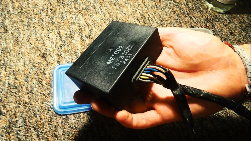
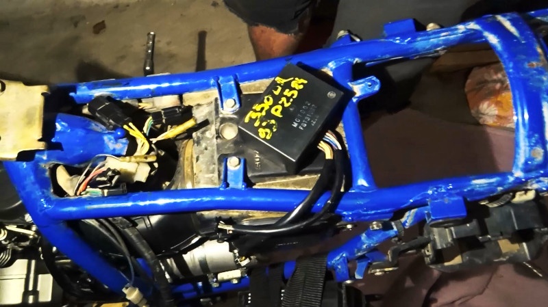
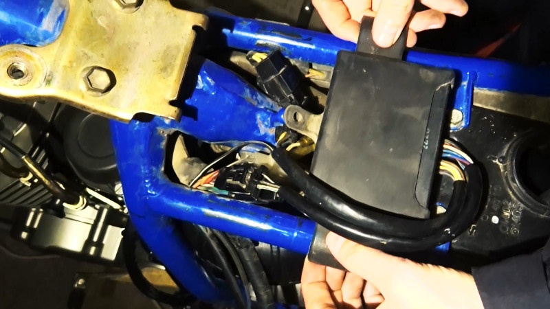
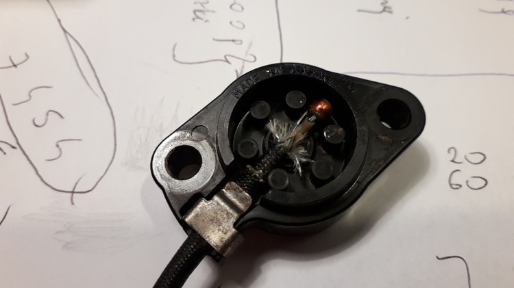
Behold the CDI unit!
The CDI (Capacitor Discharge Ignition) is an electronic ignition system, which mainly consists of three components:
- capacitor, which stores the energy
- thyristor, which allows for capacitor discharge
- thyristor triggering system, which regulates the timing of the thyristor firing according to the engine speed.
Besides those, there also few other components in the DR350S CDI, which are responsible for engine cutoff depending on the state of the ignition, the state of the neutral gear and the state of the side foot.
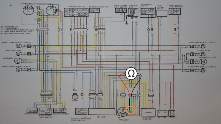
How the CDI unit looks on the wiring diagram?
Let’s take a look.
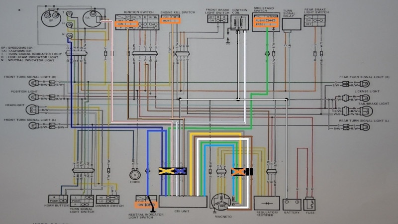
As you can see those are lots of connections! :/ However, fortunately, we can filter out some. Let’s check it wire by wire:
| 1 | blue with a black tracer wire | it is lightning the neutral gear indicator light, so we can ignore this as it’s just a light |
| 2 | blue wire | neutral switch connection, so it must be short to the ground if we want to run the bike |
| 3 | green wire | side foot cable, so we can ignore it, the bike can be started with the side foot set out anyway |
| 4 | white with the red tracer cable | it connects to the tachometer, so again we don’t have to care much if the engine start is what interests us |
| 5 | white with the blue tracer cable | it’s a ignition coil connection and it is this cable which is a path for the impulse from the discharging capacitor we’ve mentioned earlier, so it has to be connected to the CDI properly |
| 6 | black with the white tracer cable | CDI ground, hence a must-have! |
| 7 | black with the yellow tracer wire | CDI ground, hence a must-have! |
| 8 | grey wire | the first cable leading to the first coil of the crankshaft sensor |
| 9 | yellow wire | the second cable leading to the first coil of the crankshaft sensor |
| 10 | brown wire | the first cable connecting the CDI unit to the power source coil |
| 11 | white wire | the second cable connecting the CDI unit to the power source coil |
| 12 | blue cable | the first cable leading to the second coil of the crankshaft sensor |
| 13 | green cable | the second cable leading to the second coil of the crankshaft sensor |
The 8th, 9th, 10th, 11th, 12th and 13th connection from this list has to work properly if we want to ride our poor DR.
Psst… In order to make finding wires easier, here’s a little cheat sheet – mapping of wires to sockets:
4-pin square socket: connections 1-2-3-4,
3-pin single-row socket: 5-6-7,
4-pin square socket: 8-9-12-13,
single pins: 10, 11.
Before testing the CDI
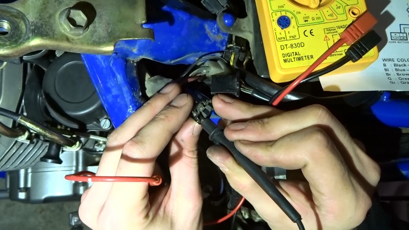
Firstly let’s start with the CDI ground test, because we omitted it in previous posts. We will test the connection resistance. Therefore first we connect our multimeter probe to the battery ground terminal.
After that we search for the 6th wire on our list above. It’s in a 3-pin socket.
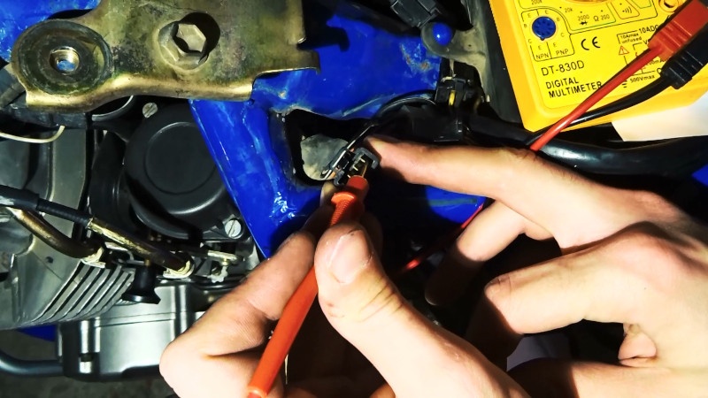
If connection is fine, then the multimeter should show 0 Ω.
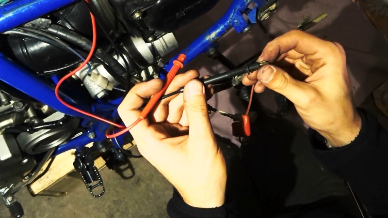
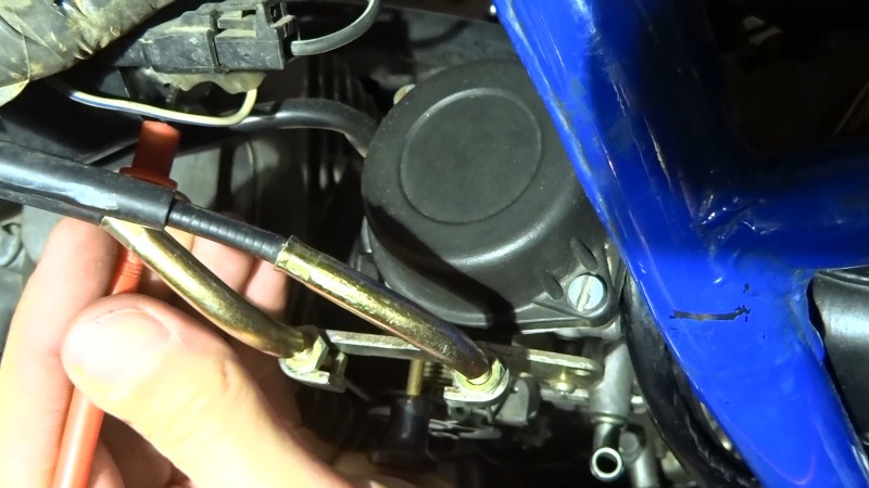
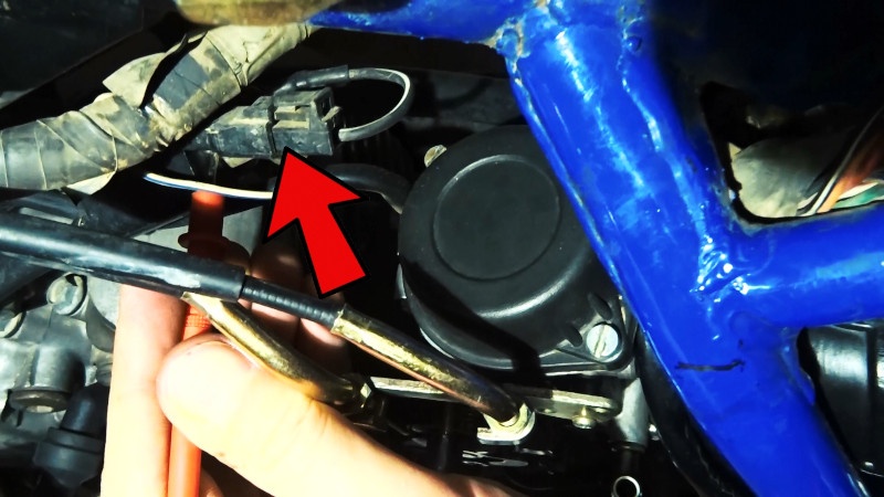
After that we can check the connection between the CDI unit and the ignition coil. Hence here we have to measure resistance between the white with blue tracer cable (in the 3-pin socket of the CDI) and the connector hanging from the coil’s casing:
Additionally we can check if the ignition coils shorts to the ground. It’s a black with yellow tracer wire.
Summing up, as a result, if everything looks fine so far and you checked the ignition coil, the power source coil, the pick up coils, the ignition switch and kill switch and the neutral switch, then I think it’s safe to move on to the real CDI unit test.
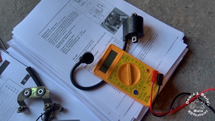
The CDI unit test
If you read our earlier posts, then I bet you’ve already guessed that the CDI test consists of the resistance measurements ;) Actually, lots of resistance measurements as you can see from our connections lists for wiring diagram above.
However we are lucky as dear Mr Suzuki included a quite easy to get around table, where all the test we have to make and their expected results are listed.
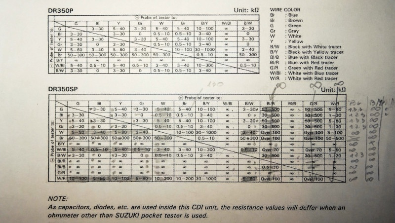
See? Easy. Firstly we just pin-up the multimeter positive probe to the wire of color listed in the given column header. Then, equally, we pin up the negative probe to the cable of color listed in the first cell of the table row. Finally to check the proper resistance value we read the intersection of the given column and row. However we have to be careful to not mess up the probe order, because for some connections there are different results for the opposite pin-up of probes.
For instance, table for our DR looked like that after the measurements:
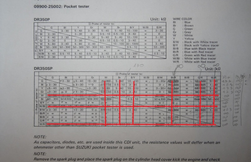
As you can see we found lots of inconsistencies in our CDI. So we had a reason to think the CDI is broken and so we bought a new one from France for about 80$ (130$ with delivery :/).
We’ve almost bought a cheaper one, but in the nick of time we acknowledged that the cheaper one has only connection to the one crankshaft sensor coil. (Note: there are 3 different DR350 CDI versions.)
That’s not all!
Out of curiosity we’ve also measured the resistance in the new (used) CDI unit and to our surprise it turned out… the measurements were completely the same as in the old CDI!
We were daunted, but in despair we gave it a try and connected the new block to our dead DR.
Finally after few kicks we saw… this!
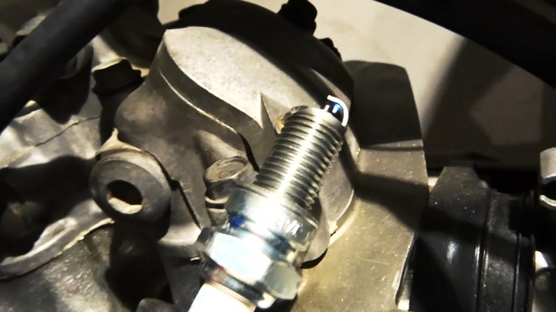
We were really relieved that we didn’t throw money down the drain!
To summarize the method for testing the CDI unit described in the service manual seems to not be so good idea. Although the multimeter measurements should make perfect sense for the CDI unit as it should be possible to detect a burnt wire etc. Sure, in the manual it is mentioned that the test should be carried with a special Suzuki multimeter, but seriously we don’t know now why the multimeter from Suzuki should make any difference in comparison to the standard multimeter in case of an ordinary resistance measurement? Or maybe there are errors in the manual?
Anyway, as always, we have a video for you from this test party
Comments