Last time we’ve checked the kill and ignition switches, but before we will make hundreds of measurements on the CDI unit, we have one more switch to test – the netural switch.
Meet the neutral switch
The neutral switch tell us that, well… there is neutral gear switched in :) I’m sure you’re not surprised ;)
As anyone who ever attempted a driving licence course knows, starting up the vehicle (be it a car or a motorbike), which isn’t switched to neutral gear will fail miserably (or end up really bad ;)). So we’ve got to check if the switch properly communicates to the rest of the electrical system that Hey, we’ve got neutral gear here!
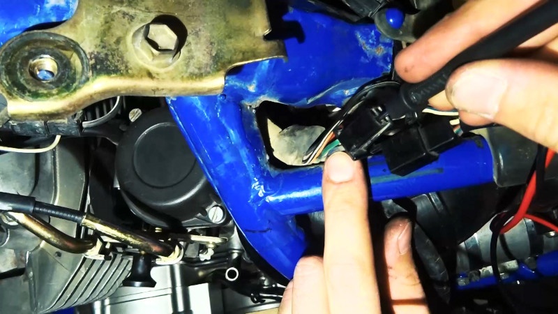
Here’s our suspect:
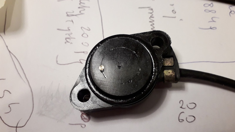
In the first picture you can see a gold contact and a drawn circle. Over this circle moves a metal pin mounted in a drum gear shifter. When the neutral gear is selected, then the pin from the drum touches contact inside the neutral gear sensor. In this case neutral gear signal cable is connected to the ground.
In other cases when the drum is coding other gears than neutral, the connection is broken, because the pin from the gear shifter drum is touching the plastic body of the neutral gear sensor instead of connector.
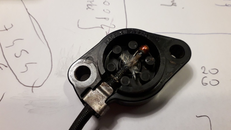
Lack of the metal pin, lack of the spring pushing the pin or damaged cable can deceive the CDI unit that we’ve shifted the gear up from neutral. When there’s a higher gear switched in, the CDI cuts off the spark and doesn’t let us turn on the engine.
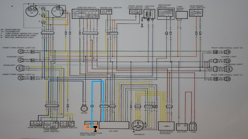
The neutral switch on the wiring diagram
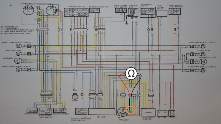
As always we can easily find the neutral switch on the DR 350 wiring diagram in the service manual.
It’s connected to the CDI by the blue wire, check it out here:
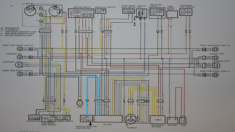
When the switch is in OFF position (any gear switched in), then it doesn’t short-circuit the signal cable to ground:
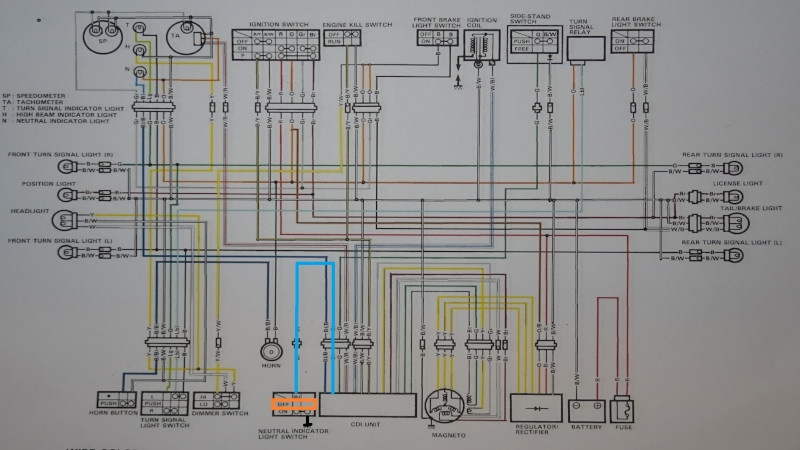
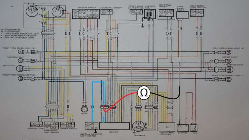
While when the switch is in ON position, we have connection to the ground:
Test setup
Our neutral switch test consists of the resistance measurement between the bike’s ground and the blue signal cable.
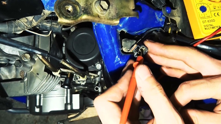
So in practice we just insert one probe under the clamp cap of the battery…
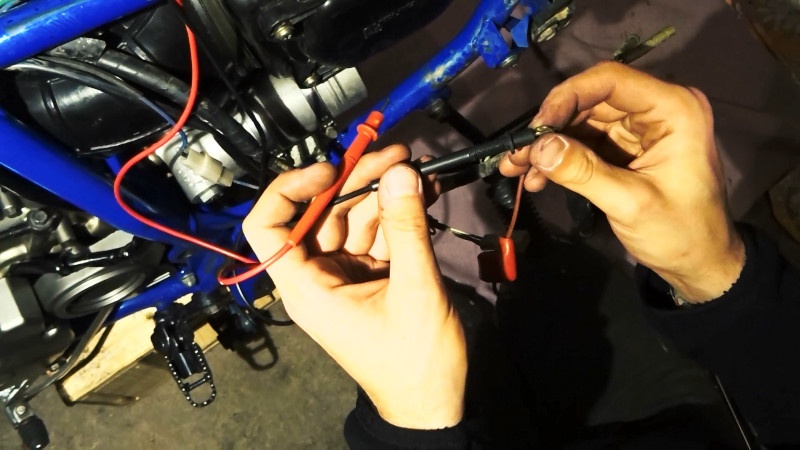
… And the other probe we pin-up to the signal cable. It is inside of one of two square contacts with 4 pins hanging around the CDI unit. Only one of them has a blue connection. This blue wire is special, because it’s the only one, which is additionally covered with cloth insulation, not only rubber insulation like the other wires.
Testing procedure
After setting up the multimeter, the testing procedure is all about checking out how the resistance changes when we change the gears. (Additionally you can spin the front sprocket to see if there is any play.) Basically we just measure the resistance with neutral switch ON and OFF.
Correctly when we have neutral switch ON (so we can spin the sprocket without any problem) the resistance should be close to 0 Ω, just like in closed circuit.
The moment we switch the gear up to 1st or 2nd gear, we should notice the resistance growth, which makes the measurement exceed the multimeter range. It’s a sign that the circuit opened like it was supposed to.
Repeating this steps few times is good idea to make sure everything works fine.
If you’re still not sure how it should be done, then check out our step by step video:
Summary
Once again it turned out that our DR doesn’t suffer from what we thought it would.
The last step and hope is checking out few extra wires for any disruptions. But if that won’t help, we can suspect that the CDI is malfunctioning.
And in our case a broken CDI is quite probable if you will take into account that we’ve already found broken spark plug cap resistor. Because of this the spark could have found some shorter and nicer way through the CDI unit and could made some wire burn as the electronics usually don’t like voltage of few thousands Volts.
We will check the CDI unit in the next post and last post about testing the Suzuki DR350 electrical system.
If you’ve missed previous posts, check them out, we’ve already made the ignition coil test, the power source coil test or the pick up coils test and the ignition switch and kill switch test.
Comments