Today lets have a chat about the switches – the kill switch and the ignition switch, exactly. (Or put another way – how to startup a motorcycle in a MacGyver style.)
Why those now?
As probably everyone already know, to turn the bike on/off we use the ignition switch or the red kill switch button.
Of course it may happen that the kill switch will stop work properly – some cable can tear apart or a contact can corrode. So today I’ll write a bit about checking the electrical system in terms of those switches.
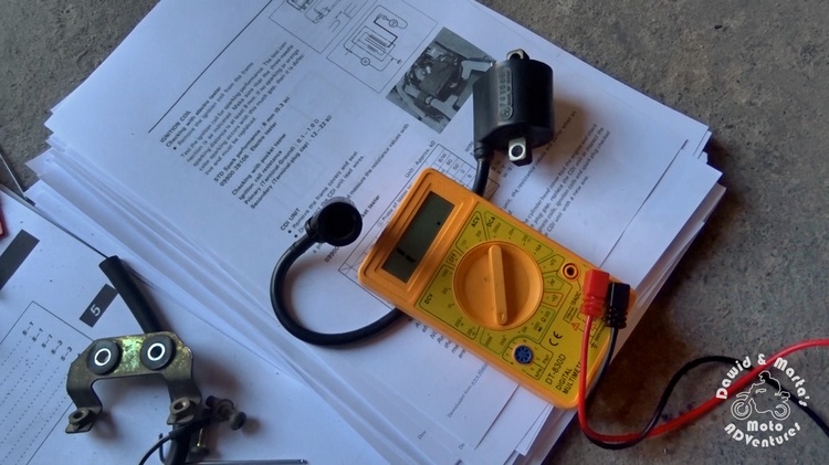
As in our recent tests, we will just use the service manual and our favourite tool so far – the multimeter.
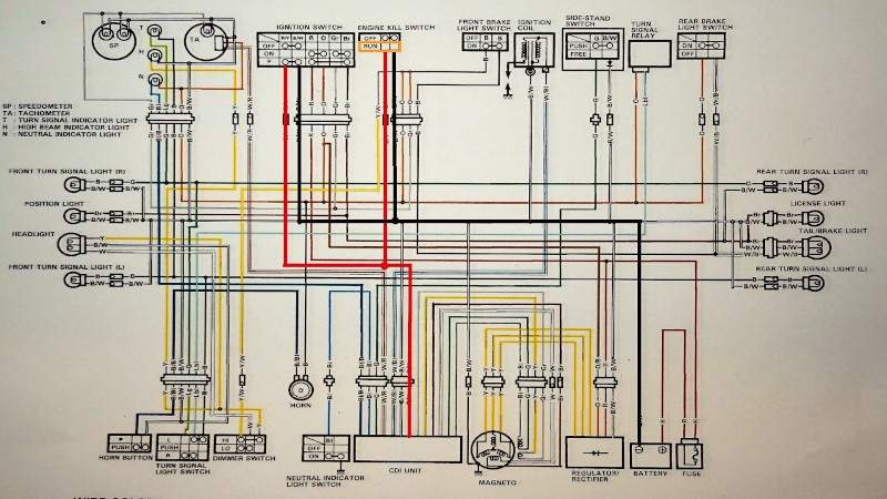
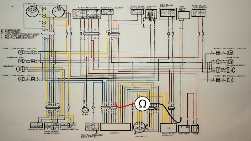
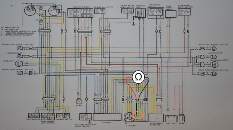
The kill switch and ignition switch on a wiring diagram
This time we’re interested in the black with yellow tracer cable. It goes from the CDI unit and branches to the ignition switch and to the engine kill switch. We coloured this wire red.
The second interesting cable is the black with white tracer cable. It goes from the ground terminal of battery and branches to the ignition switch and the kill switch. We marked it black.
See the wiring diagram below:

If you look closer at the diagram, you can notice that our switches (the ignition and the kill switch) short the signal cable to the ground in OFF position. Both are connected in parallel, so even one of them in OFF position is enough to block the engine start.
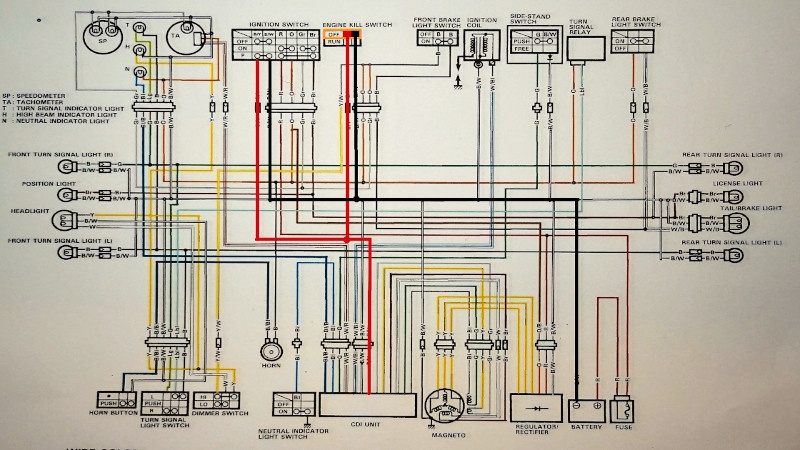
When the kill switch is in RUN mode, it doesn’t short the signal cable to the ground and everything depends on the ignition switch:
If the kill is in OFF position it shorts the signal to the ground, so that the engine stays turned off, no matter the ignition switch state:
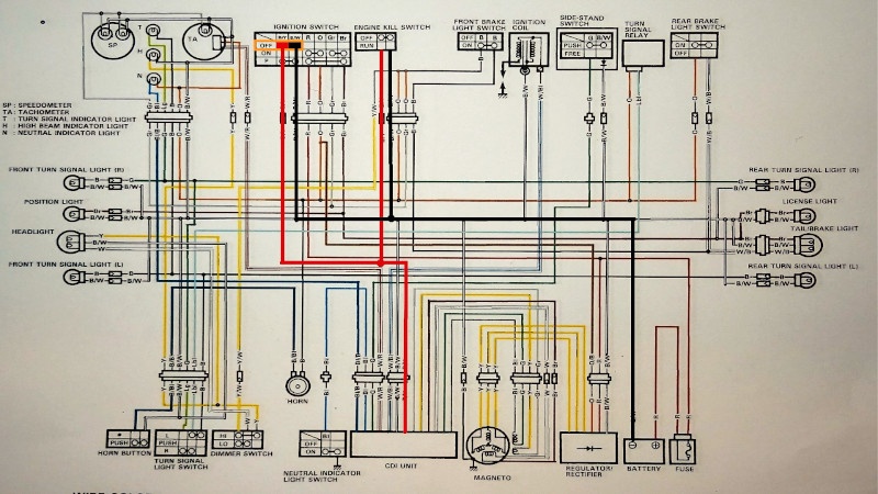
Now let’s look from the ignition switch point of view.
This time the ignition switch is ON, so it doesn’t short the signal to the ground. Everything depends on the kill switch:

When the ignition switch is OFF, so it shorts the signal to the ground, the kill switch is helpless – the engine will remain turned off:
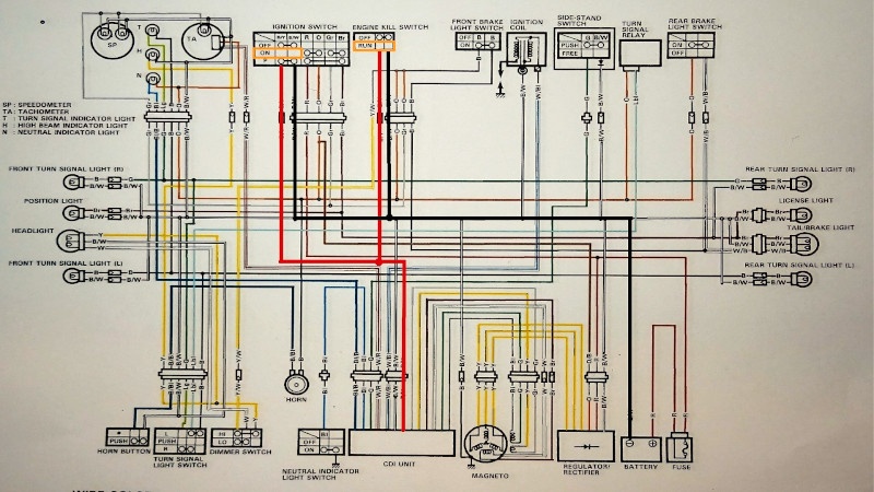
In the end, the only possibility to turn on the engine – both of interesting us switches should be in RUN/ON position. Only then the signal wire (red in the picture, black and yellow in the motorcycle) isn’t shorted to the ground. See here:
Hope you’re not tired of the theory and don’t have enough diagrams for todays, because now we’ve got some tests to run! :)
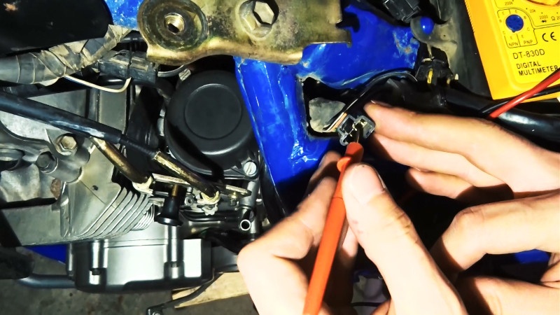
The testing procedure
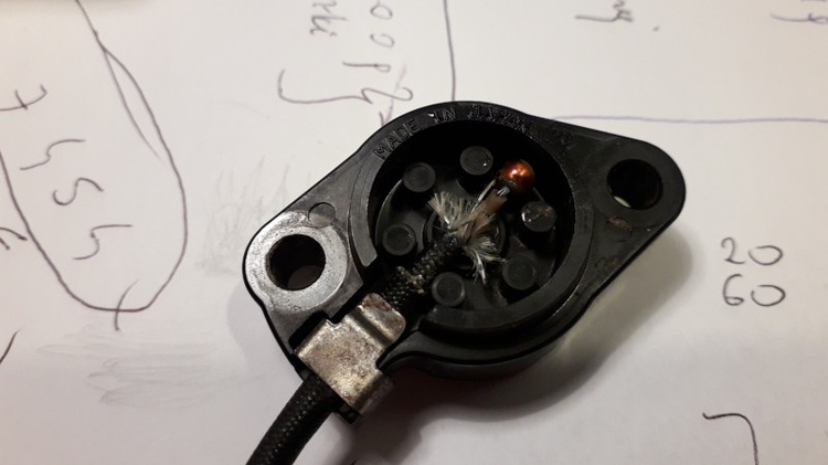
Time to switch our multimeter to the resistance measurement and pin it up to some wires. On the wiring diagram it looks like this:
Of course, we can use ground available at the CDI unit or wherever you like it.
We found the battery ground terminal the most comfortable spot.
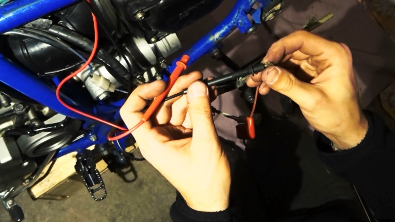
The second probe should be pinned to the only one 3-pin contact around the CDI unit. The interesting us wire is the black with the yellow tracer one.
On the wiring diagram someone drew this wire as if it is located on the contact edge. While in reality it’s in the contact center! So look for the colors carefully.
We have 4 scenarios to test with our multimeter:
- Ignition OFF, kill OFF – we expect resistance like in the closed circuit, so just few Ohms.
- Iginition OFF, kill RUN – we expect resistance like in the closed circuit, so just few Ohms.
- Ignition ON, kill OFF – we expect resistance like in the closed circuit, so just few Ohms.
- Ignition ON, kill RUN – resistance like in the open circuit, so beyond the range.
Just to be sure we can play around a little with switches and turn them on and off few times to see what’s happening on the multimeter, to be sure we can notice the resistance value change. So try to jump a couple of times from the setting 2 to the setting 4 and back, etc.
Every time we should note a change on the multimeter.
You can watch a video from this test here:
The MacGyver tip
In our DR everything was OK here and the ignition switch and the kill switch aren’t the one to blame. So in the next post we will focus on another suspect – the neutral switch.
But how do you start the motorbike in a MacGyver style? you would ask. You cut the most interesting to us black with yellow tracer cable near the ignition switch and you’re ready to go (⌐■_■) ¯\_(ツ)_/¯
First time here and also troubling with the DR electrical system and spark?
See the ignition coil test, the power source coil test or the pick up coils test.
Comments